Lookahead limiting in Pure Data
Some years ago, I started working on the implementation of lookahead limiters which I would then implement in my feedback networks for stability purposes. My original design was based on two side-chained amplitude curves: a fast one for attack transients and one for sustained sounds, which had to be slow enough as to avoid intermodulation distortion. The fast curve was based on peak envelope estimation (see below), while the slow one was based on RMS to have a smooth behaviour. The curves were in a master-slave mode so that the effect of the fast curve would decrease with regard to the growth of the slow curve: that was necessary to avoid that the processed signal would be scaled down twice by both curves.
Despite the algorithm produced good results, it needed some empirical calibrations and it also involved a rather large number of objects in Pure Data which would considerably load the CPU. Besides, I was using some objects from PD-extended and I already had in mind to migrate to Pure Data Vanilla.
A simplified design was based on only one amplitude curve calculated with a long-decay peak envelope (10 seconds). A peak envelope checks whether the input is greater than the output and, if that condition is true, it updates the peak with the new value from the input signal. Otherwise, the current peak decreases following an exponential curve and reaches a certain attenuation after a desired time which, in my specific case, is of ~60dBs. This would allow detecting fast attack transient and, at the same time, the long decay would create a smooth curve for the sustained and slow sounds.
This was a good compromise for my systems, although such a long decay is not always desirable: occasionally, that would create silences after high-amplitude impulses for the attenuating curve would decrease very slowly and the input signal would be scaled down even if below the limiting threshold.
Recently, I have decided to try the design of a limiter based on a post by IOhannes Zmölnig who, in turn, has based his design on the thesis project by Peter Falkner: Entwicklung eines digitalen Stereo-Limiters mit Hilfe des Signalprozessors DSP56001.
This design is based on a peak-hold module with an exponential decay curve and we will now see an implementation in Pure Data Vanilla.

The first step in a lookahead limiter is to delay the input signal so that the attenuating curve can anticipate fast peaks.
The amplitude profile of the input signal is obtained by combining a peak-hold module – something that holds a peak for a certain time until a new peak is detected – with a peak envelope one to have a smooth decay when signals transition to lower peaks. Here, after, the peak-hold module, I am also using a one-pole low-pass filter with a period matching that of the input delay so that peaks and input signal are synchronised and the attack is slightly smoothed out.
The scaling factors are calculated using the following formula:
out_amp = threshold / input_amp
where out_amp is the scaling factor by which the input is multiplied, threshold is the limiting target and input_amp is the amplitude profile of the input signal. Of course, we want the signals below the limiting threshold to go through unaltered (except for the delay), so we are clipping to 1 all the scaling factors which exceed unity.
The arbitrary hold and decay time of 0.1 seconds seemed to be a good compromise: theoretically, that should result in a consistent amplitude profile for signals as slow as 5Hz for that is the peak-to-peak time at that frequency, and the attenuating signal would decrease fast enough so as not to result in long silences or gaps.
The peak envelope can easily be implemented as a single feedback loop through which the detected peaks recirculate, and to calculate the right feedback coefficient for a desired decay time we can use the following formula:
0.001^((D/SR)/t)
where D is the feedback period in samples, SR is the samplerate and t is the decay time in seconds.
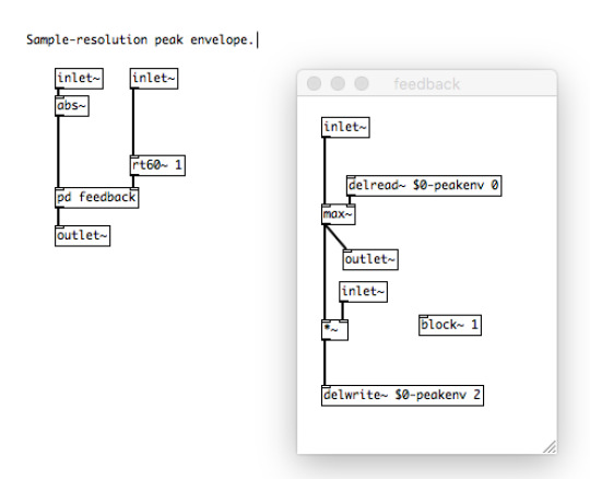
The left inlet is the absolute value of the input signal and the right inlet is the calculated feedback coefficient. We are computing the feedback loop in a subpatch with a block size of one sample to have maximum resolution in the peak envelope estimation and to be consistent even with very fast signals. This subpatch should contain only the objects necessary to compute the recursive part of the algorithm as smaller block sizes have heavier CPU loads. The [max~] object outputs the greater of two signals so we can use it to update the peak and open or close the feedback loop according to the comparison of the input and output values.
The peak-hold algorithm is a little bit less straightforward. As mentioned above, a peak-holder will check whether the input is greater than or equal to the output and, if the condition is true, it will update the peak and will reset a timer. When the condition is false, the countdown will start and, after that time, if no new peak has been detected, whatever value in the current input will be set as the new peak.
Even in this case, I have decided to implement all the algorithms using exclusively audio signal objects. [samphold~] will, of course, be very useful here. What it does is to sample the left signal whenever the right signal decreases and continuously outputs that value until a new one is sampled. This object is often used in conjunction with [phasor~], an oscillator which linearly ramps out from 0 to 1 creating a unipolar sawtooth wave. This wave decreases at each cycle so it can be used as a clock for the [samphold~] object to sample values at regular rates. Despite this seems to be useful for the timer needed in our algorithm, the phase of [phasor~] cannot be reset with signals so it is not adequate. Though a [phasor~] object can easily be implemented as an iterated incremental step and it will be possible to reset its phase using audio signals.
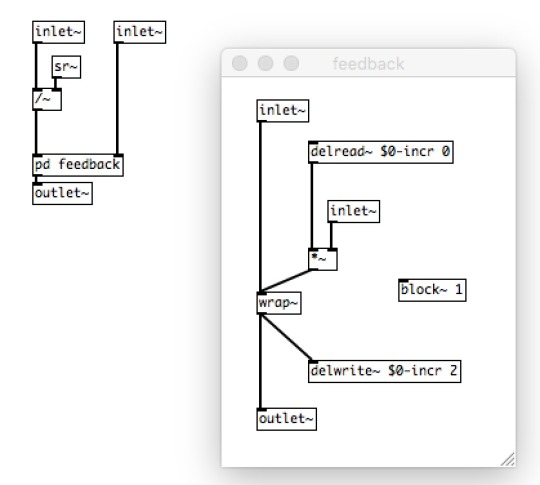
The left inlet is the frequency of the oscillator, the right inlet is a signal (which will be either 1 or 0) that will be used to reset its state. This new version of [phasor~] can now be used as a timer for the peak-hold module.
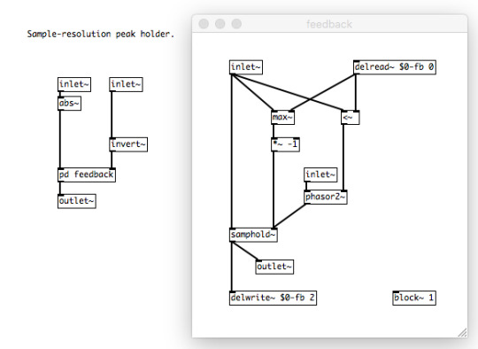
Like with the peak envelope, we calculate the absolute value of the input signal, which is the left inlet. The right inlet is the hold time in seconds converted into Hz for the [phasor2~] object.
Even here, the single-sample block size is necessary to have accurate results. We are piloting the [samphold~] object using two mechanisms comparing input and output signals. One checks if the input is less than the output. If true, the countdown starts and [samphold~] will eventually be updated with a new value if the condition does not change until the end of the countdown; if false, the input is equal to or greater than the output so the timer is reset to its initial state. The other mechanism returns the greater value between input and output. We know that, unless the countdown has reached its end and a smaller value has been sampled, the output of [max~], if it changes, is because we have an input which is greater than the output. That means that the direction of change will always be the same, i.e. increasing, and the final step to implement the algorithm is to simply multiply the output of [max~] by -1 to invert its direction so that every new peak is sampled.
Despite this design is so far the best for the general case, the computational load is still much higher than my previous limiter based on just a peak envelope module. Some of my digital projects require limiting units in several of their nodes so I probably will not be able to use this one for those, but this will certainly be preferred for projects where only the output stage will need to be limited.
My next step with lookahead limiting is probably to find an adaptive mechanism which dynamically changes the decay of the peak envelope curve based on the characteristics of the output itself, i.e. how fast the signal is, to minimise the problems related to long decays. Though these are actually not problems and they only need to be turned into formal resources.